SITUATION
The purchasing customer expressed the desire to expand its assembly thermal spray cell operations. The machine requirements included a completely autonomous system outside of loading the parts onto the carriage. The carriages will need to be designed to have a variable speed range for various thermal spray applications. Safety systems will be designed to shield the machine operators from all safety hazards.
OPPORTUNITY & IMPLEMENTATION
The proposed and final stations include:
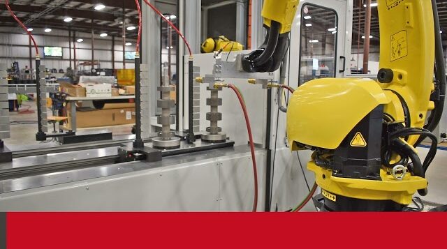
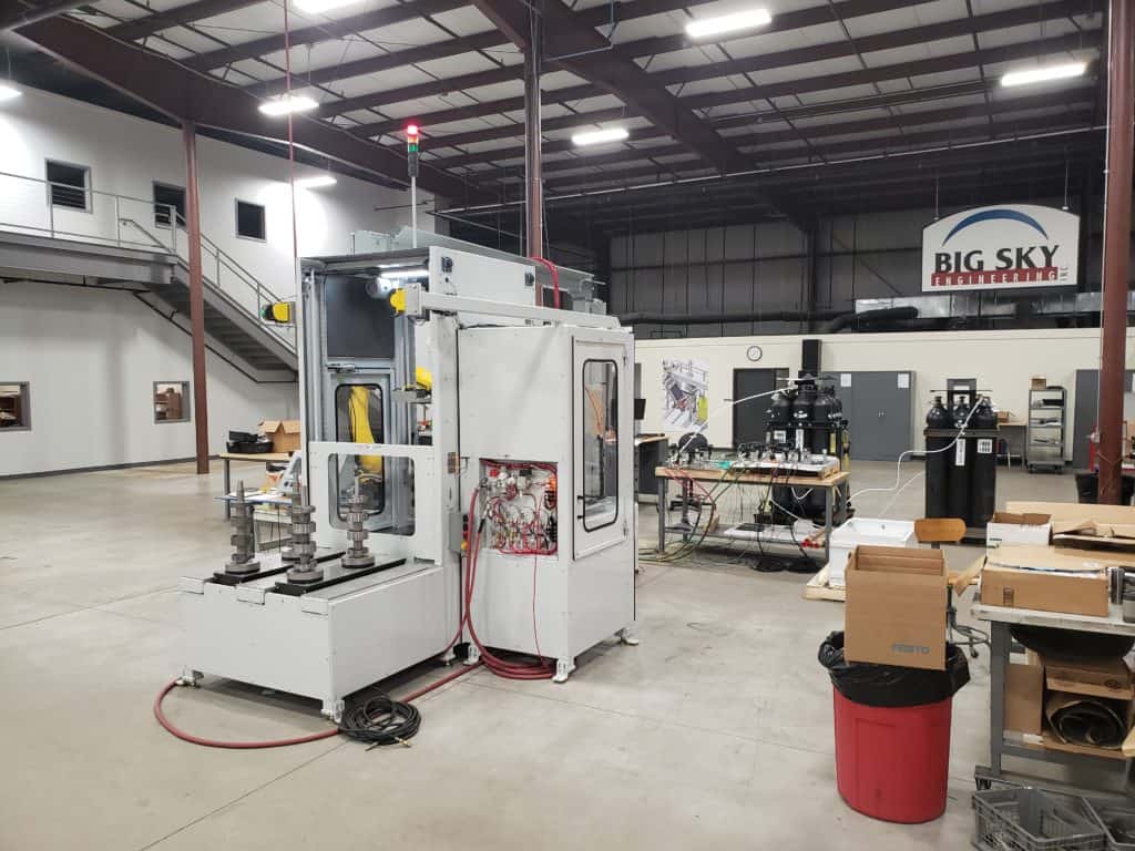
Carriage Infeed- The carriage in-feed holds 2 rows of stacked parts. The machine operator places the stacked parts on each carriage and selects the carriage pushbuttons to start the machine in producing mode.
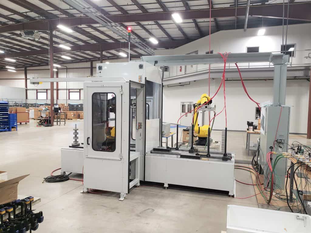
Micrometer Robot-The micrometer is mounted on the EOAT (End of Arm Tool) on the first robot cell. The micrometer measurement station is located between the entry and exit doors. The entry and exit doors shield the micrometer components from overspray, dirt, and debris.
Spray Application- The thermal spray is applied via an EOAT (End of Arm Tool) mounted on the second robot cell. Cooling towers assist in cooling the carriage parts during the spray application process.
Control Station- The machine’s control station features an HMI (Human Machine Interface), Micrometer Display, and Hard wired system control pushbuttons. The interactive display allows complete control over the functions of the machine.
DESIGN FEATURES & SPECIFICATIONS
- Spindle drives utilize servo motors for variable speed control.
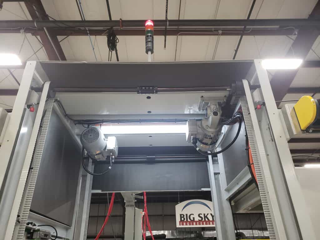
- Automated entry and exit doors shield the operator and components from thermal spray material.
- Optical micrometers are attached to the robot’s end of arm tooling.
- Safety laser scanners prevent the operator from accessing the machine cell & carriage punch points while the machine is in operation.
- Class 3 guard enclosure.
- Stack Light Indicators and audible alarms display the current machine state.
- Allen-Bradley 10” PanelView HMI
- The machine HMI uses customary pictures & buttons for control overrides. All machine sequences can be
operated in manual mode on the HMI. Current cycle rates and station information are displayed on the main
screen display.
Power Requirements: 480VAC, 3 Phase, 60A
Pneumatic Requirements: 80PSI – 10 SCFM


